Some of the links in this post are affiliate links, meaning, at no additional cost to you, I will earn a commission if you choose to make a purchase.
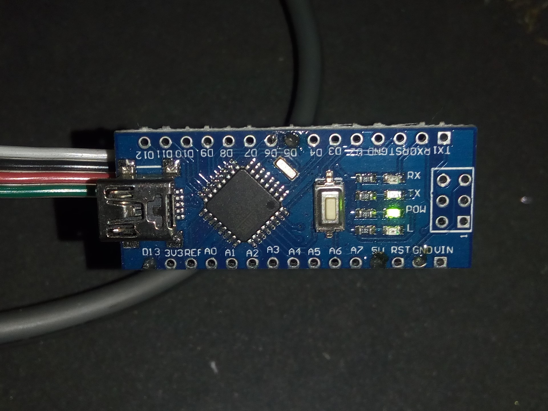
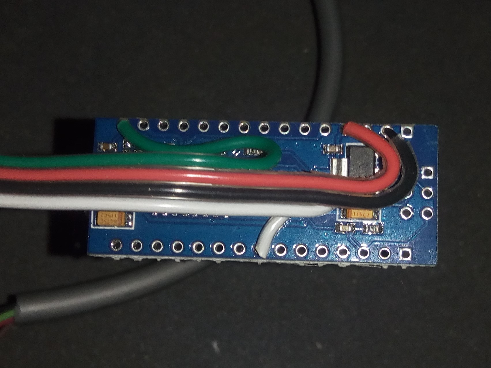
Frequency counter sketch to detect the charge pump signal from PathPilot and enable stepper drives after the controller is running. Allows for the use of a generic breakout board and a non-Tormach machine. Works well on Arduino Nano and can be easily fit into control enclosure. Note: Some of the breakout board’s outputs are reversed. It will work it just needs to be wired differently than labeled.
/*
 pathpilot_charge_pump_detector

  Hardware: Arduino Nano https://amzn.to/2Iw6Smy
            Generic Breakout bBard ://amzn.to/2VSw4b3

  Uses Timer 1 as a pulse counter to count input pulses.
  Uses Timer 2 as a 1 ms timebase to construct a gate (counting period).

  Digital pin 5 is the frequency input. Frequency measurements are
  sent to the serial port.

  Pin 13 is the output
  set to active low to enable stepper drives when signal is detected
 */

#define GATE_PERIOD 1000   // Gate period in ms
#define MAX_MHZ 5000000    // Maximum count in MHz mode
#define MAX_KHZ 999999     // Maximum in KHz Mode

volatile boolean measurement_ready = false;
volatile unsigned int overflows = 0;
volatile unsigned long freq_measurement = 0;

void setup() {
  // initialize the digital pin as an output.
  // Pin 13 has an LED connected on most Arduino boards:
  pinMode(13, OUTPUT);
  // Initialise serial port
  Serial.begin(9600);

  // Zero counters
  TCNT1 = TCNT2 = 0;

  // Set timer 1 to count pulses on D5 pin
  TCCR1A = 0;
  TCCR1B = _BV(CS11) | _BV(CS12);
  // Enable Timer 1 O/F interrupt
  TIMSK1 = _BV(TOIE1);

  // Set timer 2 to count 125 ticks from the 16 MHz clock
  // with a prescaler of 128. This give a tick every 8 us
  // and thus an overflow every ms.
  TCCR2A = _BV(WGM21);
  TCCR2B = 0;
  OCR2A = 124;
  // Enable Timer 2 Match Interrupt
  TIMSK2 = _BV(OCIE2A);

  // Reset prescaler
  GTCCR = _BV (PSRASY);
  // start Timer 2 with a prescaler of 128
  TCCR2B =  _BV (CS20) | _BV (CS22) ;
}

// Timer 1 interrupt.
// This counts the number of times the counter has overflowed.
ISR (TIMER1_OVF_vect)
{
  overflows++;
}

// Timer 2 Interrupt
ISR (TIMER2_COMPA_vect)
{
  static unsigned int ticks = 0;  // Tick counter (counts milliseconds)
  static unsigned char led_state = 0;
  unsigned char OF_flag;  // Holds the state of timer 1 overflow flag.
  unsigned int timer_value;  // The sampled value of timer 1
  unsigned long new_pulse_count;  // The total number of pulses so far.
  static unsigned long old_pulse_count = 0; // The number of pulses last time.

  if( ++ticks > GATE_PERIOD )
  {
    // Reset ticks counter. This if-statement is true once every gate period.
    ticks = 0;

    // Read Timer 1
    // Need to check to see if the counter overflows
    // while we're in the act of reading it. If it does
    // we just read all over again.
    do {
      OF_flag = (TIFR1 & TOV1);
      timer_value = TCNT1;
    } while( OF_flag != (TIFR1 & TOV1) );
    // If there was an overflow deal with it here
    // NB This ISR has a higher priority than Timer 1 overflow.
    //    This means that the Timer 1 interrupt can't run while this
    //    interrupt is executing.
    if( OF_flag )
    {
      overflows++; // Count the overflow
      TIFR1 |= _BV(TOV1); // Clear the interrupt
    }
    new_pulse_count = ( (unsigned long)overflows << 16 ) + timer_value;
    // Set measurement ready flag
    if( !measurement_ready )
    {
      freq_measurement = new_pulse_count - old_pulse_count;

      measurement_ready = true;
    }
    // The new pulse count this time becomes the old pulse count last time.
    old_pulse_count = new_pulse_count;
  }
}

void loop() {


  // Wait for measurement ready
  while( !measurement_ready )
  {;}

if(freq_measurement < 450 || freq_measurement > 550)
{digitalWrite(13, LOW);   // LED off
}
else {digitalWrite(13, HIGH);   // LED on
}

    Serial.println(freq_measurement);

  measurement_ready = false;

}